


News
News Test Systems
How do you test the testing process? Automated cross-checking of the test program
Test equipment capability should tell you whether a piece of equipment is capable of performing certain tests or measurements within the framework of its specifications. Unlike simple mechanical components, where only a caliper is needed for measuring the diameter of a turned part and the parameters for test equipment capability are simple and clear, electronic tests using an in-circuit tester are far more complex. Because in addition to the actual testing device, the test system, the fixture and the test program itself have a great effect on the test equipment capability and thus need to be considered together.
However, these calculations are highly complex since they also mutually influence each other. Whether the test system, the adapter and the test program provide the desired testing depth and fault coverage in a stable manner depends on many parameters. Test systems are configurable, i.e. various settings can be adjusted to achieve the measuring result. Typically, a program generator uses a bill of materials and connection list to perform a circuit analysis and use this to create a test program with all the necessary parameters such as stimulus, guard points, integration times, delays and Kelvin measurements. The program generator does not know the parasitic hidden components in complex IC's and cannot consider them in its calculation. Therefore, the result does not always have the desired success. This is then detected during so-called "debugging" and parameters are modified, i.e. adapt and change the parameters of the automatically generated test program and until the desired measurement value is provided in stable form. These manipulations can certainly be used to force a measurement value without actually having measured anything reasonable.
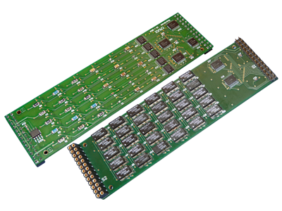
One fatal consequence of this is that a component is measured even though it is incorrectly placed or even missing! This means that the expected fault coverage is correct only in theory. How does one prevent this? By manipulating each individual component, i.e. “unsoldering” it or replacing it with components having different values and verifying each change made using the test program to determine what is actually being detected. Even for a small assembly with 100 components this quickly becomes a time-consuming and error-prone exercise. With the small component shapes and high densities used today, this is an additional challenge.
Is it better to use “incorrect components” on the assemblies to provoke a fault in order then to recognize whether the complex “test system-fixture-test program” is capable of detecting these faults?
Which solution seems to make sense here?
Digitaltest has now developed a procedure that allows other components to be inserted in series or parallel with the measured component during the measurement so that the nominal value of the test object can be changed. If an additional resistor is inserted in parallel with the resistor to be measured, the measuring result should be lower or, in the case of a capacitor with connected parallel capacitance, correspondingly higher. Now if you insert a whole string of components and each time take a measurement and evaluate it, this should also be reflected in the change to the measurement value. If not, then we have this famous “ticket” and must assume that a fault in this component is not being detected. Now we have the opportunity to change the parameters for this measurement such that faults are detected or to take the measurement completely out of the test and replace it with other means.
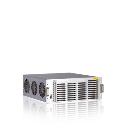
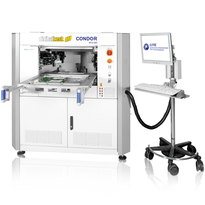
Now, this new procedure can be implemented with FailSim automatically in our testsystem. A new board with a string of resistors and capacitors is plugged into the new AMU05 (Analog Measurement Unit) and can be inserted into the measuring bus in series or parallel for each measurement. Thus these components can be connected to the components to be measured during each measurement and errors can be simulated. After the first measurement of the component the software automatically calculates the resistance or capacitor to be connected based on the actual value of the component in order to manipulate the measurement, so that it is outside the tolerance in both directions. These values are now switched on and thus the desired errors are provoked and checked. Using evaluation software, the recorded measured values are compared and evaluated with regard to the actual fault coverage determined. The result is a clear confirmation of stable and reliable measurements which are also capable of finding defects.
It remains to be noted: Testing software is an important factor for the success of a system. Accordingly, a variety of techniques and tools exist today to simplify this process. It is tested to verify different goals: Requirements, economic efficiency, usability - or even faultlessness. And a test program and test system cannot be verified better than with FailSim. Quod erat demonstrandum!
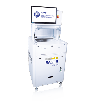
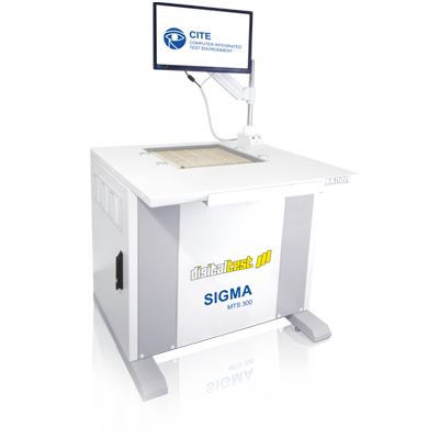
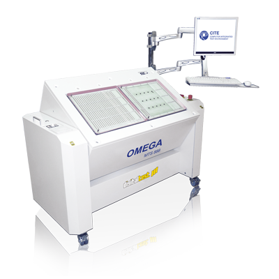
The FailSim module is available for all Digitaltest systems in addition to many other expansion modules.
For example, for the Sigma MTS 300: Simply find the right extension for your test strategy in the "Modules" tab.
